Blogs
Why LiDAR Mapping Accuracy Alone Is Not Enough
Delivering Engineering-Ready Topographic Data for Civil Design
LiDAR mapping has transformed the way topographic data is collected. Today’s systems can generate millions of data points with vertical accuracies measured in centimeters. However, a critical misconception persists in the industry:
“High point density and nominal accuracy do not guarantee usable engineering data."
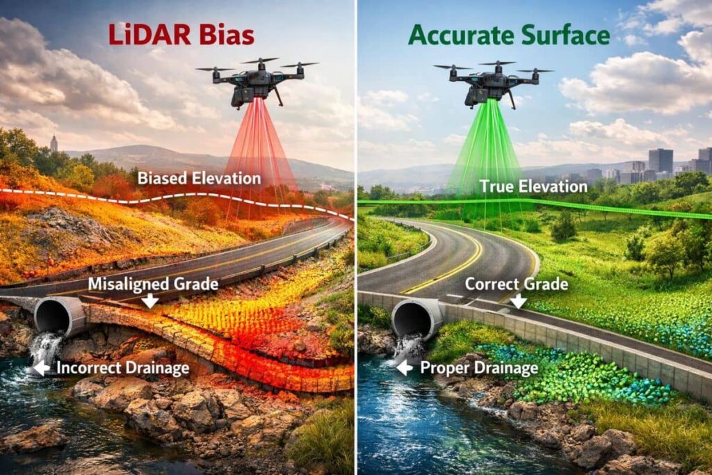
In reality, many LiDAR datasets—despite meeting stated accuracy standards—fail to perform reliably in civil design workflows due to issues such as:
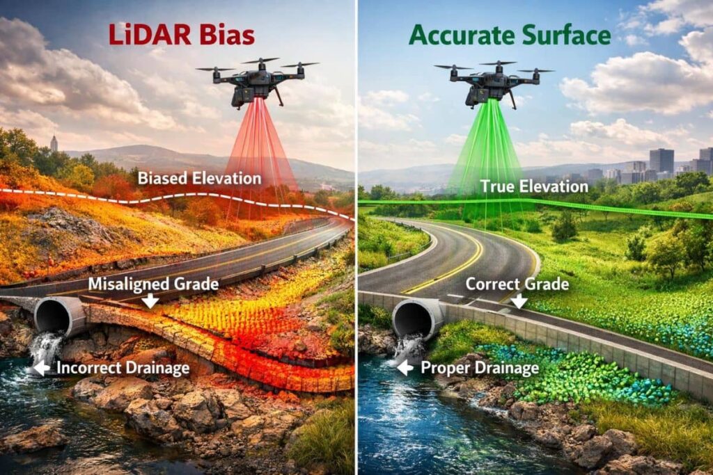
Vertical bias
Poor control integration
Incomplete breaklines
Lack of surface interpretation
For developers, engineers, and project stakeholders, these shortcomings translate into:
Increased construction risk
Grading inconsistencies
Drainage failures
Cost overruns
This paper explains the key risks in modern LiDAR mapping and outlines how a professional, survey-controlled approach produces design-ready deliverables that reduce risk and improve project outcomes.
The Evolution of LiDAR in Civil Engineering
LiDAR (Light Detection and Ranging) technology has rapidly advanced over the past decade. Drone-based LiDAR systems now provide:
Dense point clouds
Rapid data acquisition
Access to difficult terrain
As a result, LiDAR is widely used for:
Site development
Corridor mapping
Flood studies
Solar farm design
However, the rapid adoption of LiDAR has also introduced inconsistent data quality across providers.
The Core Problem: Accuracy vs. Usability
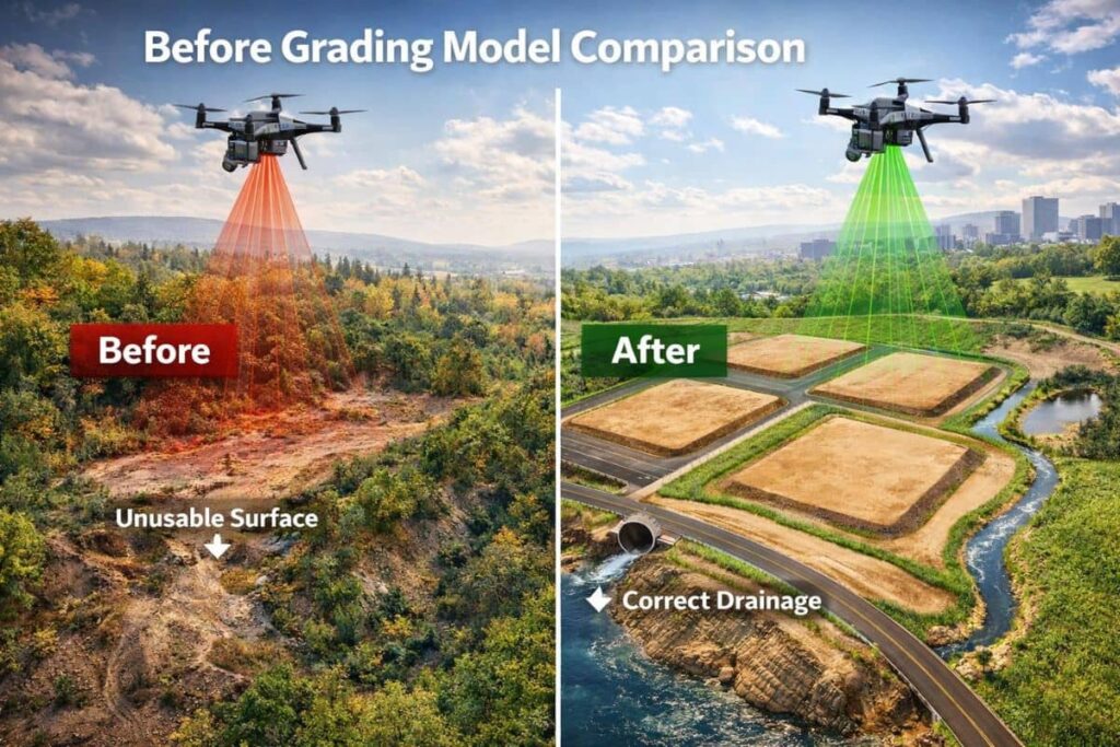
Many LiDAR providers focus heavily on reported accuracy metrics, such as:
±0.10 ft vertical accuracy
RMSEz compliance
Point density (points per square meter)
While these metrics are important, they do not address a more critical question:
“Can the dataset be used reliably for engineering design?"
Why Accuracy Alone Is Misleading
A dataset can meet statistical accuracy standards and still contain:
Systematic vertical bias
Misaligned flight lines
Surface noise in flat areas
Incomplete terrain definition
These issues are often not visible in raw point clouds but become obvious when the data is used in design software.
Critical Risk #1: Vertical Control Inconsistency
The Hidden Risk in Elevation Data
One of the most significant issues in LiDAR mapping is inconsistency in vertical control.
Common causes include:
Poor GNSS base station positioning
Improper geoid model application
Reliance on outdated benchmarks
Mixing project datums
Why This Matters
Even small vertical discrepancies (0.10–0.20 feet) can impact:
Drainage design & stormwater flow
Sanitary sewer design and connections
Earthwork quantities
ADA compliance
Real-World Impact
Projects have experienced:
Misaligned grading plans
Drainage structures set incorrectly
Rework during construction
These issues are not caused by poor design—but by inconsistent survey control at the data stage.
Critical Risk #2: Systematic LiDAR Bias
Bias vs. Random Error
In LiDAR datasets, there are two types of error:
Random error – acceptable and expected
Systematic error (bias) – dangerous and often unnoticed
Bias can occur due to:
GNSS trajectory drift
Calibration errors
Incorrect vertical datum application
Why Bias Is More Dangerous
Random noise averages out. Bias does not.
A consistent vertical offset can:
Shift entire surfaces
Misrepresent grades
Distort cut/fill calculations
Key Insight
A dataset with low noise but high bias is far more dangerous than one with higher random variation.
Critical Risk #3: Inadequate Surface Interpretation
Raw Data vs. Engineering Data
Many LiDAR deliverables consist of:
Point clouds
Basic classifications
Minimal breakline definition
However, engineering design requires:
Continuous surfaces
Defined drainage paths
Accurate edge conditions
Common Deficiencies
Typical issues include:
Missing drainage breaklines
Poor curb and pavement definition
Disconnected terrain features
“Floating” surface elements
Critical Risk #4: Model Sensitivity in Modern Design Software
Modern civil engineering platforms are extremely sensitive to surface data.
What Has Changed
Today’s design tools:
Analyze surfaces at a fine resolution
Generate automated grading
Model drainage behavior
What This Means
Small inconsistencies in LiDAR data can result in:
Surface artifacts
Erratic grading behavior
Incorrect drainage paths
Key Insight
Modern design software amplifies data errors that previously went unnoticed.
The Shift Toward “Design-Ready” LiDAR Deliverables
The industry is moving away from simply delivering raw LiDAR data.
Today’s Expectation
Clients increasingly expect:
Survey-controlled datasets
Fully interpreted surfaces
Engineering-ready models
What Defines a Design-Ready Deliverable
A high-quality LiDAR dataset should include:
1. Verified Survey Control
Proper horizontal and vertical datum
Independent check points
GNSS validation
2. Bias-Free Elevation Data
Calibration and QA/QC procedures
Cross-checking against ground truth
3. Complete Breakline Network
Drainage features
Edge of pavement
Curb lines
Channel definition
4. Clean Surface Modeling
Reduced noise in flat areas
Smooth transitions
Continuous terrain representation
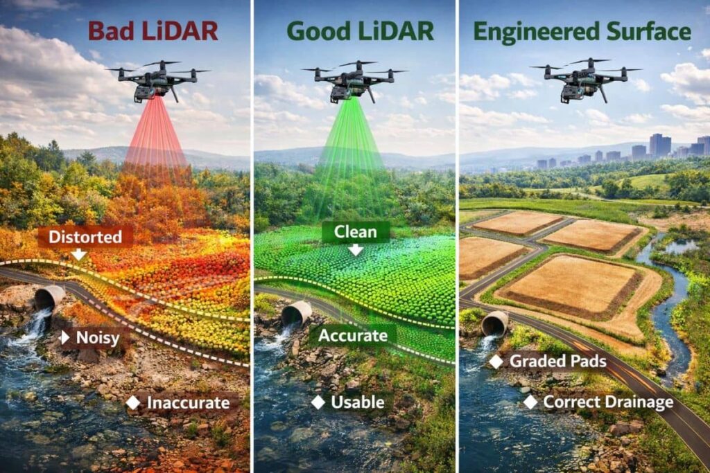
Our Approach: Engineering-Grade LiDAR Mapping
We approach LiDAR mapping as a surveying and engineering problem—not just a data collection task.
1. Survey-Controlled Workflow
Every project begins with:
Established ground control
Verified benchmarks
Proper datum alignment
This ensures consistency across:
Design
Construction
Future expansion
2. Rigorous Calibration and QA/QC
We implement:
Boresight calibration checks
Flight line overlap analysis
Independent accuracy validation
Our goal is not just to meet accuracy standards—but to eliminate systematic bias.
3. Engineering-Level Surface Interpretation
Unlike typical LiDAR providers, we deliver:
Fully defined breaklines
Drainage-aware surfaces
Design-ready terrain models
4. Integration with Civil Design Platforms
Our deliverables are specifically prepared for use in:
Civil design workflows
Grading plans
Drainage modeling
This reduces:
Rework
Design uncertainty
Project risk
Boresight — Definition (LiDAR & Surveying Context)
Boresight refers to the precise angular alignment between a LiDAR sensor and its navigation system (IMU and GNSS) within a mapping platform.
In practical terms:
“The boresight defines the exact direction the laser is pointing relative to the aircraft or drone’s orientation."
Plain-English Explanation
Think of boresight as:
The “line of aim” of the LiDAR scanner
The reference direction the system assumes the laser is firing
The link between where the sensor is pointing and where the system thinks it is pointing
If that alignment is even slightly off, the computed coordinates of every point will be wrong.
Why This Matters for Your Project
Reduced Risk
Eliminates costly surprises during construction.
Improved Design Confidence
Engineers can trust the data from the start.
Better Project Outcomes
Accurate surfaces lead to accurate decisions.
Case Applications
Our LiDAR services are particularly valuable for:
Solar Farm Development
Large-area terrain modeling
Precise grading requirements
Commercial Site Development
Drainage-sensitive projects
Complex grading plans
Infrastructure Projects
Corridor mapping
Roadway design
Conclusion
LiDAR mapping has become an essential tool in modern civil engineering—but not all LiDAR data is created equal.
The difference between a standard dataset and an engineering-grade deliverable comes down to:
Control
Calibration
Interpretation
Quality assurance
“The true value of LiDAR is not in how much data is collected—but in how reliably that data supports design and construction."
References
American Society for Photogrammetry and Remote Sensing (ASPRS). (2014). Positional Accuracy Standards for Digital Geospatial Data.
Federal Emergency Management Agency (FEMA). (2021). Guidelines and Specifications for Flood Hazard Mapping Partners.
National Geodetic Survey (NGS). (2022). Blueprint for the Modernized National Spatial Reference System.
National Oceanic and Atmospheric Administration (NOAA). Geoid Models and Vertical Datum Guidance.
U.S. Geological Survey (USGS). (2020). LiDAR Base Specification Version 2.1.
American Association of State Highway and Transportation Officials (AASHTO). Digital Project Delivery Guidelines.
Construction Industry Institute (CII). Digital Transformation in Construction.
Autodesk. Civil 3D Surface Modeling Documentation.
Bentley Systems. OpenRoads Designer Terrain Modeling Guidance.

LiDAR Mapping Pro
Professional LiDAR mapping. Accurate data. Reliable results.
Email: [email protected]
Phone: 1-888-376-6770


Our Services
Business hours
Mon: 9am to 5pm
Tues: 9am to 5pm
wed: 9am to 5pm
Thurs: 9am to 5pm
fri: 9am to 5pm
Copyright 2026. Auburn Business - CE, LiDAR and Private Utilities. All rights reserved.